

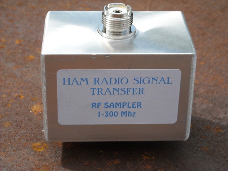
Ham Radio Signal Transfer
TESTED TO 10 KW, READY TO SHIP!
DIRECT FROM THE MANUFACTURER.
Feed Through, 0.01% loss passive device.
so-239 connectors for use with PL-259 connections on Ea side,
BNC tap on top to connect scope or other device.
Available with So-239 or N connectors.
No ground loops Built tough, Unlike others Not a Bud box full of capacitors ! 100% Ground Isolated Sampling
Inductive pickup system
INTRODUCTION:
Unlike other Very Cheaply built, unreliable, possibly dangerous samplers We are built to last; with NO capacitors and NO Ground loops.
Unlike ANY other, Our product's sampling electronics are totally isolated from the signal path and ground.
The scope gets to use it's own ground reference, with a safety factor like no other.
This allows NO possibility of Short circuits, Screen shadows and Ground loops.
Truly shielded feed through design, Resulting in Reduced impedance anomaly's and losses.
Obtain's True Lab calibrated Sample with No guess work.
NOT a demodulated sample prone to inaccuracy.
Calibration so accurate it is used by many as a watt meter, when hooked to a scope it is more accurate than a standard watt meter.
True PEP output readings are easily obtained.
If you were looking for a cheap handy box full of caps, you are in the wrong place !
USING YOUR SAMPLER
Place the sampler in the RF Coax line after any amplifier, before the antenna.
Connect the unit to the RF line using the So-239 connectors on ea side of the unit.
Station output connects to one side and antenna connects to the other side.
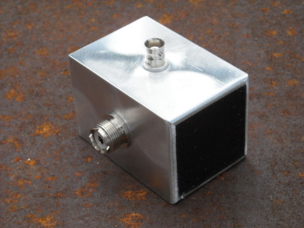
Connect a BNC Cable to the Isolated BNC connector on top of the unit,
one end connects to the sampler and the other end to your scope.
Turn your scope Sweep time to 2 Ms.
For AM use, set the scope sensitivity to read the carrier as 2 divisions unmodulated.
100% will be 4 divisions total at full modulation.
200% will be 6 divisions total.
With SSB signals, seldom should you see a flat topping waveform; if the signal flat tops, as shown in the over modulated SSB photo, your signal will be very wide and nasty sounding.
With Am signals, seldom should you see the center line show as you modulate your station; if you see the center line, you are over- modulating.
If you see flat topping in the Am mode, that is an indication of a lack of head room.
It is a must to look at the signal as it is, before the antenna. Looking at it any other way WILL NOT help you understand the true nature of your signal.
WAVEFORM'S
To understand what you are looking at on the scope, look to the photos above showing the various wave forms.
The first photo after the photos of the device is a proper SSB signal 100% modulated.
The second is an SSB signal over-modulated.
The third is an AM carrier unmodulated.
The forth is an AM signal 100% modulated and symmetrical.
The fifth is an AM signal 140% Pos. and 98% neg proper phase,
The sixth is an AM signal improper phase 140% neg 98% pos.
You can tell all you need to know about your stations signal with a simple scope and this device.
For AM use, set the scope to read the carrier as 2 divisions unmodulated.
100% will be 4 divisions total at full modulation.
200% will be 6 divisions total.
With SSB signals, seldom should you see a flat topping waveform; if the signal flat tops, as shown in the over modulated SSB photo, your signal will be very wide and nasty sounding.
With Am signals, seldom should you see the center line show as you modulate your station; if you see the center line, you are over- modulating.
At that time, splatter will occur, causing your signal to become much wider and nasty.
If you see flat topping in the Am mode, that is an indication of a lack of head room.
It is a must to look at the signal as it is, before the antenna. Looking at it any other way WILL NOT help you understand the true nature of your signal.
This devices' sampling electronics are isolated from ground, so the scope is looking at its own ground potential in partner with the sampling electronics.
The case of this device is grounded to your radio station ground potential.
Built to last with no capacitors or parts to age and go bad, the only way to have a failure is to greatly over power or break the connectors off .
If you would like to use a product that will not blow up, stop working or change suddenly this is it.
Proudly made in the USA!
Repeatable Reliable Results.
Specifications:
RF rating: 10 KW PEP 1-30Mhz = / = 5 KW 30-150 Mhz =/= 2KW 150-300 Mhz
1 KW = 1.4 v peak to peak +/- 5% @BNC Port
100 Watts =140 Mv Pp@ BNC Port
*At higher freq. above 15 Mhz you will see slightly more signal voltage to your test equipment.
This is per design.
Flat response +/- 5% from 1 Mhz To 15 Mhz.
If a correction chart is need for harmonic testing above 15Mhz one will be provided.
Design Impedance: 50 Ohms (can be used with changes in accuracy from 15 -600 ohms)
(de-rate power to 5 kw above 100 ohms; de-rate to 2 kw above 300 ohms Load)
Loss: 0.01% or less
No Computer needed
BNC Sampling Port
SO-239 Antenna/Radio Connections
Currently used in 5 countries &42 US states.
1 year replacement warranty (electronics only, excludes connector damage or intentional damage).
Designed to last 20+ years in continuous service.
This product allows you to sample small amounts of RF from the line to send to a scope, freq. counter or other devices.
Sample RF without stray signal in the shack, no ground loops, no capacitors, clean honest sample.
All passive electronics are encapsulated with electronic epoxy potting compound, inside a robust machined aluminum chassis.
Connectors are the best available RF rated so-239 connectors.
10 KW PEP rating with nearly no loss, thanks to the feed-through design.
Overbuilt and tested under extreme conditions.
Each unit tested to 10 KW PEP before shipment.
May be used indoor or outdoor.
Dimensions: 2"x2"x3"
HAM RADIO SIGNAL TRANSFER , RME 43 OR ANY PARTNERS WILL NOT BE RESPONSIBLE FOR ANY INJURY OR DAMAGE TO ANY PERSON, PLACE OR THING RESULTING FROM THE MISUSE OF THIS DEVICE.
To order from GigaParts, click link:
http://www.gigaparts.com/Product-Lines/Wire-Ant-Analyzers/Ham-Radio-Signal-Transfer-RF-Sampler-1-300Mhz.html
To order from e-bay, direct from the manufacturer, click link:
http://www.ebay.com/itm/121185757133?ssPageName=STRK:MESELX:IT&_trksid=p3984.m1555.l2649
To order from Henry Radio, click this link:
http://store03.prostores.com/servlet/henryradio/the-853/New-RF-Signal-Sampler/Detail
OR
See information on contact page to order.
Products are new in box.
Chassis Machined In-house
Solid walls of 1/8" Thick Robust machined aluminium.
See bottom of page to order from authorized distributors.
Solid walls of 1/8" Thick Robust machined aluminium.
See bottom of page to order from authorized distributors.